Europe’s Rail Newsletter – June Edition Stay up to date with the latest developments in European rail innovation in...
EU-Rail June 2026 Newsletter
read more

A body of the
European Union

Access the list of all EU-Rail Calls for Proposals.

On 21 June 2024, the Governing Board of Europe’s Rail Joint Undertaking (EU-Rail) adopted a Call for Expression of Interest (CEI) with a view to selecting associated members with the potential to contribute to the achievement of its objectives. The Governing Board decision can be accessed here.
Discover detailed information about procurment rules and information.
Access detailed information about past tenders.

Europe's Rail regularly published Calls for Tenders. To find out about open Calls, follow link below.

Article 15 (Principle of transparency) of the EU-Rail financial rules states that the JU shall make available on its internet site no later than 30 June of the following financial year information on the recipients of funds deriving from its budget.

EU-Rail’s Innovation Pillar (IP) is tasked to deliver operational and technological solutions that contribute to a more efficient, flexible, and demand-led, yet safe and environmentally sustainable European railway system.

The System Pillar provides governance, resource, and outputs to support a coherent and coordinated approach to the evolution of the rail system and the development of the system view.

The Deployment Group advises the EU-Rail Governing Board on the market uptake of rail innovation developments and support their deployment.
For a successful and effective implementation of the Digital Automatic Coupler for European rail freight (DAC), it is of crucial importance to have open, close and efficient cooperation between rail stakeholders. The European DAC Delivery Programme enabled by Europe’s Rail, offers a unique European platform for such cooperation and collaboration.
Discover how Europe’s Rail Joint Undertaking is calling for a bold, coordinated investment strategy to simplify and modernise rail systems across the EU. This public-private partnership model – outlined in our High-Level Paper – proposes an €18 billion investment from 2028 to 2034 to strengthen European competitiveness, deliver greener transport, and drive technological sovereignty.

The Shift2Rail Joint Undertaking is the predecessor programme of the Europe's Rail Joint Undertaking (EU-Rail), established by Council Regulation (EU) 2021/2085 of 19 November 2021.

Discover detailed information on Europe's rail innovation initiatives, showcasing flagship and other projects aimed at enhancing rail systems across Europe. It highlights collaborative efforts funded by the European Union to develop sustainable, efficient, and competitive rail transport solutions.

Europe’s Rail Catalogue of Solutions illustrates successful R&I results in the form of possible products and solutions, while highlighting the benefits for final users, operators, infrastructure managers and/or suppliers. This publication also outlines the advantages of integrating demonstrators into market solutions so that they can deliver the rail innovation Capabilities of the future.
Europe’s Rail Joint Undertaking (EU-Rail) is the European partnership on rail research and innovation established under the Horizon Europe programme (2020-2027) and the universal successor of the Shift2Rail Joint Undertaking.

Find out the full list of Europe's Rail Members.

Discover the full structure and governance of Europe's Rail, including the decisions of the Governing Board.

Get access to Europe's Rail main reference documents, including Annual Work Plans, Annual Activity Reports, Annual Accounts and other important information.
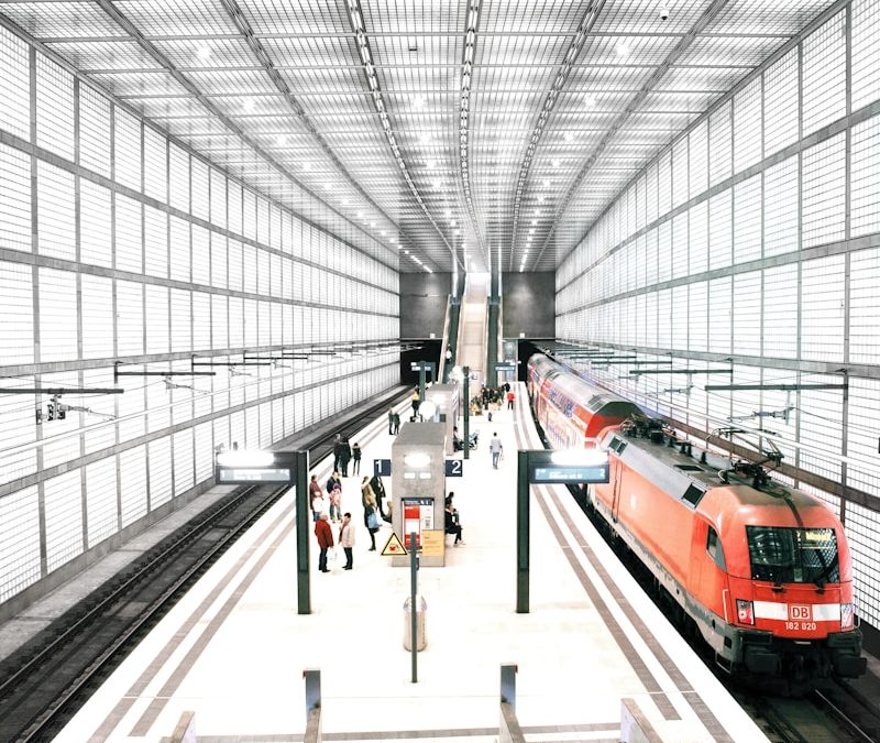
Trams, metros, and regional and high-speed trains are all important components of a public transport system. They also have the potential to reduce transportation’s carbon footprint and, in doing so, help deliver a carbon-free future. This potential lies largely within these vehicles’ electric propulsion systems.
Novel electric propulsion systems offer an opportunity to reduce energy consumption, weight, volume, and maintenance costs. Unfortunately, the electronic technology currently used in traction drives is based on silicon (Si) materials like insulated-gate bipolar transistors (IGBT), which face some significant limitations.
Silicon Carbide (SiC) is emerging as a new alternative to Si materials, one that can provide high-speed switching and lower losses. As such, SiC-based devices are being investigated for their ability to optimise traction systems.
At the forefront of this effort is the Traction System Technical Demonstrator (TD). With the goal of paving the way towards new, more efficient traction system architectures, the TD developed five demonstrators (demos), each of which is based on SiC technologies.
AC traction-system used on dual system tramway
Discussion
This demo looked at the effect SiC technology has on an AC traction system used for dual system tramways, with a specific focus on how it impacts energy consumption, weight, and volume.
The demonstration was performed first on a simulation, the results of which served as the basis for a new traction system designed to replace the IGBT with a SiC metal-oxide-semiconductor field-effect transistor (MOSFET).
The demonstrator compared the Si- and SiC-based systems in as close to real-world conditions as possible.
Key findings
As to the impact on the traction system, the use of SiC-based converters resulted in twice the power density than a Si-based system. The former also saw a 25 – 30% reduction in losses (depending on the mission profile).
In terms of impact on the transformer, the SiC-based system reduced the number of windings by two and leakage inductance by 75%. Although weight increased by 5%, the SiC MOSFET led to a 15% reduction in mission profile losses and a 20% reduction in transformer losses.
Other key findings include:
SiC vs Si
Main parameters of the optimised traction system based on SiC technology compared to a Si-based system (converter and transformer used on tram).
Conclusion
SiC MOSFETs have the potential to improve traction systems. Based on the required vehicle performance, power supply data, and electromagnetic compatibility (EMC) requirements, the technical parameters of the line converter and transformer were defined. By carefully optimising the system design and addressing electromagnetic compatibility requirements, this technology can enhance performance while reducing both energy consumption and the overall size of the system.
Next Steps
Metro traction system with SiC technology
Discussion (a) – SiC-based traction system
To provide metro rolling stock with more efficient, lighter, and smaller equipment, this demo evaluated a full SiC-based traction system installed on an Euskotren unit. The goal was to demonstrate how the use of SiC-based technology can reduce volume, weight, and maintenance costs while also increasing energy savings and reliability. This was done via three tests:
More details
During lab tests, four different load profiles were simulated to compare losses of the SiC-based equipment versus the Si-based equipment. Losses were reduced by between 800 W and 1350 W (depending on load profile). This corresponds to an energy savings of 2.43 to 5.91%. The demo concluded that the combination of the optimal flux strategy to the motors and using SiC technology can achieve a 2900 W improvement over Si-based equipment.
Key findings
Discussion (b) – SiC devices and other powertrain stages
The demo also looked at the benefits of using SiC devices in other stages of the powertrain, including the DC/DC and input AC stages. As to the former, the proposed DC/DC converter for a DC-link voltage of 1800 V using SiC technology cuts weight in half while also reducing volume by 40%. It further achieves a 50% efficiency increase. As to the inductor, improvements include a 50% reduction in weight, 37% decrease in volume, and 14% increase in efficiency. More so, because the SiC-based converter’s cooling system requires lower airflow, lower acoustic noise is emitted by the fan. It also means reduced power consumption (between 53 to 65%, depending on the configuration). A similar analysis was performed for an input stage operating in a 15 kV AC system, with a particular focus on its impact on the transformer design.
Conclusion
Using SiC technology offers significant opportunities to improve efficiency at different stages of the traction system (AC/DC and DC/DC converters, phase inductors, transformer). Furthermore, the use of SiC MOSFETs is fully compatible with current infrastructure and peripherals.
AC traction system with SiC for suburban application
Discussion
The solution includes SiC-based converters, a main transformer, and a traction motor. It is configured based on a single axle drive, car motion cooled converter, high-capacity line converter with parallel 800A SiC devices, and a high-capacity motor converter with one 450A SiC module per phase per motor. The traction converter unit consists of two converter front sections, with a middle section between. Each front section contains equipment for individually driving two traction motors (single axle drive). The converters use 3.3 kV / 800A SiC power modules. The demo conducted simulations aimed at optimising the main transformer, as well as the traction motor. As to the latter, the goal was to achieve a design that both minimised energy losses and reduced the motor’s weight compared to the base system. The target was to achieve a 5% weight reduction for the entire traction system.
Key findings
Conclusion
The prototype AC traction system for suburban applications addresses key customer requirements, including reducing maintenance, energy and overall costs; decreasing volume, weight and noise; and increasing reliability.
Full SiC sub-system on regional train SiC prototype
Discussion
The prototype consists of newly developed components covering the full traction SiC sub-system – from the pantograph to the wheels – for an AC catenary voltage. The traction system includes:
The entire traction system was validated on a specific test bench capable of reproducing the French catenary system of 25 kV/50 Hz and 1500 V DC. Specific tests, inspections, calculations, simulations, and mock-ups were performed to assess that the system met all requirements and performances before moving to train validation tests, which took place using an XCD regional train. The train is compatible with 1500V DC and 25 kV/50 Hz contact lines, with a maximum speed (during testing) of 140 km/h + 10%.
Key Findings
Conclusion
The new full traction sub-system based on SiC high-power density converters, high efficiency transformer, and high-speed motors and gear box can improve the performance of the entire traction system.
HST traction system integrated in train based on independent rotating wheels
DiscussionAfter reviewing different options, ranging from three to eight motorised independent rotating wheels, including six to 16 motors and a per motor power rating ranging from 170 kW to 450 kW, the demo selected a 350 kW option.Called MK5, the Permanent Magnet Synchronous Motor (PMSM) was designed for direct drive configuration with high efficiency. It can fit onto a Talgo train’s single axle running gear, thus enabling a different concept from a motorised conventional bogie. All the motor’s parts (rotor, stator, skewed magnet ring, pole-to-slot ratio) were optimised by taking the best trade-off between electrical and mechanical characteristics. Apart from the motor’s new components, some existing components (wheel, axle, and box) were modified to adapt to the new wheel motor. The solution was tested under different ambient conditions.
Key findings
Three types of wheelsets were compared:
The motor on wheel solution provided up to 60% of the maximum brake required in emergency, reaching 2.6 kNm during 100 seconds per wheel without sustaining any damage.The solution with four motorised axels combined with a wheelset with a third brake disc provides 7.9% and 15% more braking effort in high and low stages respectively.The results for motor and inverter efficiency showed good agreement with expected values. The exception was at very low torque, where small errors in the calculated inverter losses could give rise to significant errors in the calculated value.
Developed wheel motor parameters
Conclusion
While the motor’s measured efficiency is lower than expected, it nonetheless achieves the desired speed/torque performance. This positions the motor as a potential solution for achieving improved traction system performance at the train level, such as an interoperable high speed of 360 km/h (vs 330 km/h) with increased power at wheels of 10.9 MW (vs 8.8 MW) and based on distribution traction with an independent rotating wheelset.
Next Steps
Paving the way to more efficient traction systems
By developing new, SiC-based traction components and subsystems, the Traction System Technical Demonstrator has successfully paved the way towards more efficient traction system architectures, including for use in metro, regional, and high-speed trains.